
Use Case Diagrams
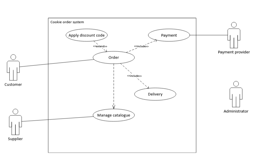
Imagine you are designing a digital ordering system for a local cookie business. Customers can browse an online catalogue of freshly baked cookies, choose their favourites, and place an order. Every order must be paid for and delivered to the customer’s address. Occasionally, a customer may enter a discount code during the ordering process.
The system also supports the people running the business. The supplier keeps the cookie catalogue up to date, for example by adding new flavours, changing prices, or marking cookies as unavailable. An administrator manages the catalogue as well and monitors incoming orders. The system communicates with an external payment provider to process payments and with a delivery service to arrange delivery.
You would create a UML use case diagram for the Cookie Ordering System by identifying the actors and use cases, placing the use cases inside the system boundary, and choose appropriate relationships. In particular, you would consider which actions are always part of placing an order and which action occurs only in certain situations.
Starting Points
Key Points
- You are able to determine when to use the Use Case diagram
- You are able to identify the actors and functions for the diagram from a case description
- You are able to draw a correct Use Case diagram
- You can explan the difference between the various types of relations; extends, includes.